Showing posts with label Electronics. Show all posts

Wednesday, 7 November 2018

Population of the Low Voltage Power Supply boards for the upgrade of the Tile Calorimeter of the ATLAS detector

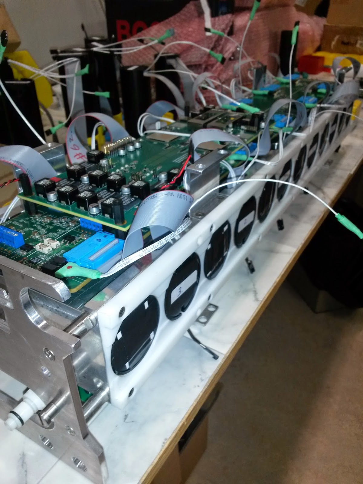
Below are some pictures of the population of the Low Voltage Power Supply boards for the upgrade of the Tile Calorimeter of the ATLAS detector. These boards will be sitting on the detector and will provide power to critical components of the on-detector electronics. The population is taking place at Jemstech

http://www.jemstech.co.za

The PCBs were manufactured in Trax

http://www.trax.co.za


Below is the final installation of the thermal posts on a slab of 8 boards


Thursday, 17 September 2015

Wits participation in the ATLAS Tile Calorimeter demonstrator expert week: 7 – 11 September 2015

Last week Dr Oscar Kureba (Postdoc) and Charles Sandrock (Chief Technical Manager) of the Wits school of Physics took part in the expert week organized by the Tile Calorimeter group of ATLAS at CERN. The main goals of the expert week were: 

Electronics:
  • Debugging the problems and instabilities observed in the single clock domain firmware,
  • Measurements  and characterisation of the clock at the CDCE output on the DBs. Jitter, etc,
  • Integrate the Demonstrator/TPP into a  TTC/DAQ partition,
  • Insert the demonstrator into the module and  perform the inter calibration  with the Cs source.

Mechanics:
  • Follow up the construction of the lifting tools and the test qualification by CERN safety experts.

Oscar worked on the electronics while Charles was involved in the mechanics side. In a nutshell, it was a fairly successful expert week as nearly all the goals were met. The demonstrator tests gave the most impressive results to date. However, more still needs to be done in fine tuning of the firmware before the upcoming test beam period (7 – 21 October). Below are some pictures, just to give a feel of the proceedings throughout the said week.

Programme of the week

Men at work: Testing hardware and firmware of the super ReadOut Driver (sROD). 

TileCal front-end electronics demonstrator, before insertion into the Hadronic module for the performance of a Cs calibration

Some of the experts during one of the morning meetings to strategise for the day ahead. 


Friday, 27 June 2014

Helping out with ATLAS Tile Calorimeter Demonstrator

In May this year I moved to CERN in Switzerland for 3 months as part of my studies at University of the Witwatersrand. I have since joined the ATLAS Tile Calorimeter Demonstrator project Group and been helping out where I can. Their aim has been to design, build and install a Hybrid Demonstrator prototype that will replace the aging front-end electronics from 1 to 3 slices of the ATLAS TileCal before RUN 2 begins in 2015. 

The entire LHC is in the process of being upgraded, by 2024 Phase II will begin where the beam energy will be increased to √s = 14 TeV and particle luminosity by a factor of 5. This will potentially address the unsolved mysteries such as dark matter. The demonstrator system needs to be fully compatible with current detector electronics as well as act as a validation for the new read-out architecture (Hybrid Design). Once fully upgraded the data output from the ATLAS TileCal will increase by 200 times to estimated 40 Tb/s!!

Earlier this month CERN had its second TileCal expert week of the year. Experts from around the world came together to help with the build of the first fully assembled Hybrid Demonstrator “Superdraw” prototype. A superdraw is composed 4 separate “minidraws” each that are independent in terms of power, readout and configuration. A total of 45 PMTs, 4 Motherboards, 4 High voltage Cards and 4 Daughter boards were needed to be assembled and connected together. The week was very successful with many new problems being identified as well as confirmation that all the components fitted together correctly and that the entire draw was able to fit in a slice of TileCal. Below are a few photos from that weeks assembly.


Newly built PMTs ready for use.


 Fully Assembled Minidraw.

Demonstrator Superdraw ready for testing.


 Insertion of the Draw into a Test Slice of the TileCal.

Tuesday, 28 January 2014

The High-performance Signal and Data Processing workshop took off on Monday January 27th. The workshop puts together astronomy, astro- and particle physics to address common issues pertaining to the Big Data problem. Attendance has been very nice with over 135 people registered, out of which 60 are students from different parts of the country. Below is the workshop picture:


Tomorrow start the hands-on sessions with FPGA-based electronics.


Friday, 6 December 2013

Current Measurement Board

Since we are interested in power measurements for the different ARM platforms, I decided to quickly design and build a simple current measurement board that we can connect an oscilloscope to to plot current (and hence calculate power with a corresponding voltage measurement on the second channel).

The concept is based on Ohms law: the voltage across a resistor is equal to the resistance multiplied by the current through it. The board design in the schematic caters for a known 0.01 Ohm resistor with a 1% tolerance and a gain of 100 with a 1500 Hz low pass filter. The gain of 100 results in a voltage output that is proportional to the current: 1 A current gives 1 V output. This is so that we can use the oscilloscopes built in multiplication to see power in real-time. The low pass filter is there so that we don't get too much noise on the current measurement, but still enough response to see a spike when we start benchmarks.

I have posted images of the schematic and photos of the finished board. If you would like the Cadsoft Eagle design files, I'm happy to share them - just put a request in the comments below. Something I should also mention is the op-amp is pretty high end, unnecessarily! To be honest, it is a free sample that I gratefully received from Maxim, so I used it...

Specifications:
Input Current: ~50 mA - 5 A
Output Voltage: ~50 mV - 5 V (dependant on how close to the negative / ground rail the op-amp can go)
Frequency Response: -3 dB @ 1591 Hz
Supply Voltage: 5 V (dependant on the op-amp)
Power Loss in 0.01 Ohm Resistor @ 5 A: 0.25 W (one can use a spreadsheet to compensate for this error)


Saturday, 30 November 2013

Complete Wandboard Array

Following the previous posts regarding the installation of HPL on the Wandboard and Cubieboard2 and the subsequent setup of the two Cubieboards connected and running HPL I am pleased to share that we have set up five Wandboards running Ubuntu 13.05 Server (Thanks to Martin Wild) and using MPICH2 as the MPI.

If you would like details on how to set up multiple boards please view my post of setting up the Cubieboard2 "array" here.

Getting things ready


The Wandboards arrived with out power adapters. We decided to build our own using a normal PC 300W power supply as this provides proper grounding and if there are static discharges against the boards they will be better protected.

Here is the first power connector we made. The green strip is a small two channel PCB board.
 The cable is standard two core cabling with a plug at the end which fits the Wandboard sockets. I used extra long spacer screws so that we could stack the boards on top of each other. They had to be spaced wide enough that the heat wouldn't be an issue and so that we could get fingers at each board in case we need to add hard drives.

Stacked array of the Wandboards

Now before connecting the power I had to write pre-made images to the sd card for each board Once I had one board up and running I then copied the SD card to the remaining four and set each IP address. There were a few issues with this which ill speak about at the end. Once the board were all up I connected everything together.

Completed Array


Wandboard array with power and Ethernet
 Now following similar procedures as my previous posts I set up HPL over a shared drive using NFS and I configured the HPL for neon and hardfp. I ran a quick test on the array using a small problem to test if all boards would indeed respond correctly. I was happy to see that all five boards showed xhpl in the processes (top) when I ran HPL.

Five terminals showing active processes when running HPL

Next up


I tried to compile ATLAS for the Cubieboard2 using neon-vfpv4 but the compiling got stuck at the L1 cache due to an infinity popping up somewhere. I will recompile that using just neon and do something similar for the Wandboard. This will improve performance quite a lot as I am using a standard ATLAS library at the moment. Once that is done I will be able to start tuning the HPL.dat file for the array.

Problems Encountered


An interesting problem came up when I copied the OS from one SD card to the other. During boot it would take exceptionally long and after finally starting up there would be no Ethernet. I checked for the adapters using ifconfig -a and they were named eth1 or eth2... not the default eth0. After doing some investigating it was quite obvious... When Linux boots up it searches for the devices and saves them in the following file:

/etc/udev/rules.d/70-persistent-net.rules

Since the hardware was changing it was appending the new hardware to the end of this list. Thus the system searched for the first one and then moved onto the next. Simply removing the content and restarting solved this issue.

Another issue was the locals. I am not sure why this one popped up but after some reading through some material I just generated the locale and reconfigured it. Using the following commands:

sudo locale-gen fi_FI.UTF-8
sudo dpkg-reconfigure locales

Wednesday, 20 November 2013

EDM Connector Altium Library

The Wandboard uses something called an EDM Connector to connect the mezzanine board to the base board. This connector is actually a standard MXM3.0 connector used by graphics cards in laptops. Some people over at http://www.edm-standard.org/ have begun work on developing a standard that uses this connector for multimedia and other general signals - which is exactly why the Wandboard implements this standard! Download the PDF from their web site and check it out!

I was unable to find any schematic libraries on the internet for this connector, including in the Altium libraries! Thus, I was forced to make one. I'm making it available for free use - but if you improve it please share your improvements with me, and others. The footprint is based off both the Foxconn and JAE datasheets which can be found at Digi-Key and Future Electronics.


Edit:
Note that the JAE connector will not work for the EDM standard as some of the E3 and E4 signals are not present, which means the ethernet will be unimplemented. The connector is mostly the same though. You can see the notch to the left of the picture above - this should not be there.

The JAE connector should work. The missing signals from the notch to the left of the connector are as follows: E1-10, E2-10, E3-1, E4-1. These are VCC and GND signals which are elsewhere on the connector. We can assume that the board connected is using a ground and power plane so this should not adversely affect operation.

Here's my link on Google Drive: MXM3.IntLib. You should be able to download it without already having Google Drive yourself. Google might try open it in Google Docs - I'm not sure why - but click on File -> Download and you will get the actual file!

Friday, 15 November 2013

Prototype of LED board for the front-end electronics test-bench of the ATLAS TileCal

The first certified prototype of the LED board for the front-end electronics the new test bench of the ATLAS TileCal is now available at Wits.

Expect next and final iteration next week and delivery to CERN early December.


Thursday, 14 November 2013

Conclusions from first Back-end Front-end integration excercise


The following is the outcome of the first Back-end Front-end integration exercise:
  • The communication between Daughterboard (front-end) and the Super Read-out Driver, sROD, emulator (front-end) has been successfully tested.
  • Achieved upstream and downstream flow.
  • Two different platforms were used as sROD emulator: Xilinx Virtex 7 and Xilinx Kintex 7. Obtained satisfactory results with both evaluation boards.
  • An overnight test has been performed to spot potential transmission errors. No error was identified after 14 hours. 

Tests have been performed between an external PC and the readout chain using an IP bus:
  • An IP bus interface has been integrated in the design of the sROD emulator.
  • This facilitates easy access to hardware registers in the sROD emulator over ethernet. 
  • Different communication tests have been performed successfully using the IP bus interface, allowing to use the external PC to read and write registers in the sROD emulator. 


Tests communication between the Daughterboard and the Mainboard:
  • Commands and data words have been transmitted from the sROD emulator to the daughterboard using the IPbus interface.
  • The Daughterboard processes and transmits the commands and data to the Mainboard.
  • This test was not completely successful. The daughterboard reacted to the commands received over IPbus, but not in the expected way.
  • Bug probably in the state machine that decodes the command into specific actions for the Mainboard. 

Next integration session will take place in December at CERN.

To the right, Pablo Moreno, from Wits.


Tuesday, 12 November 2013

First attempt to integrate Back-end and Front-end for the TileCal upgrade

Today we attempted for the first time to integrate the Back-end and Front-end of the new upgraded TileCal electronics. Work performed in collaboration with IFIC, Stockholm University, University of Chicago, Argonne National Laboratory and CERN. In the picture one can see the daughter board that will sit on the detector, connected with FPGA evaluation boards that serve as simulators of the future sROD.